Press Hydraulic Stages:
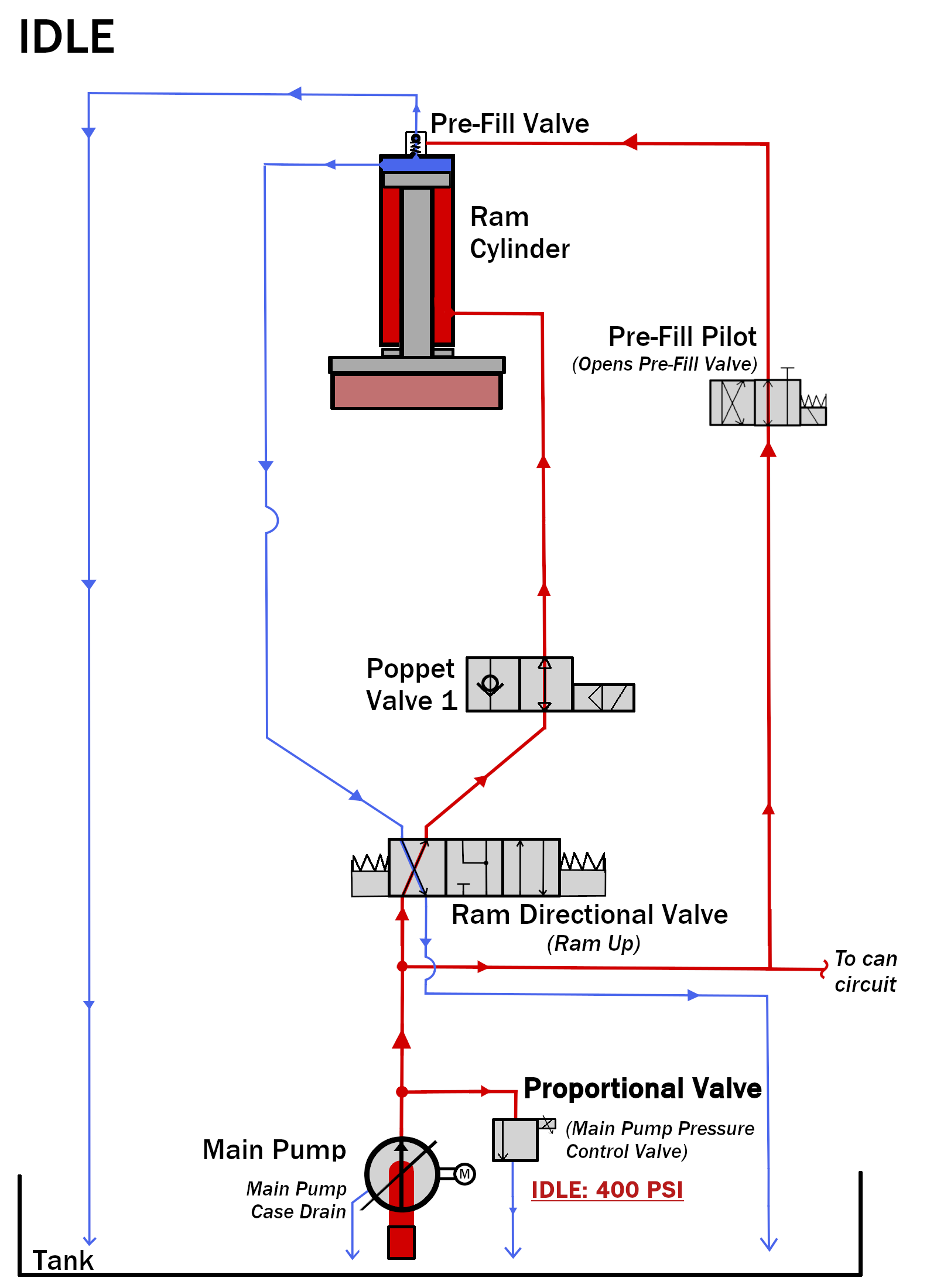
- Idling (Waiting to Load)
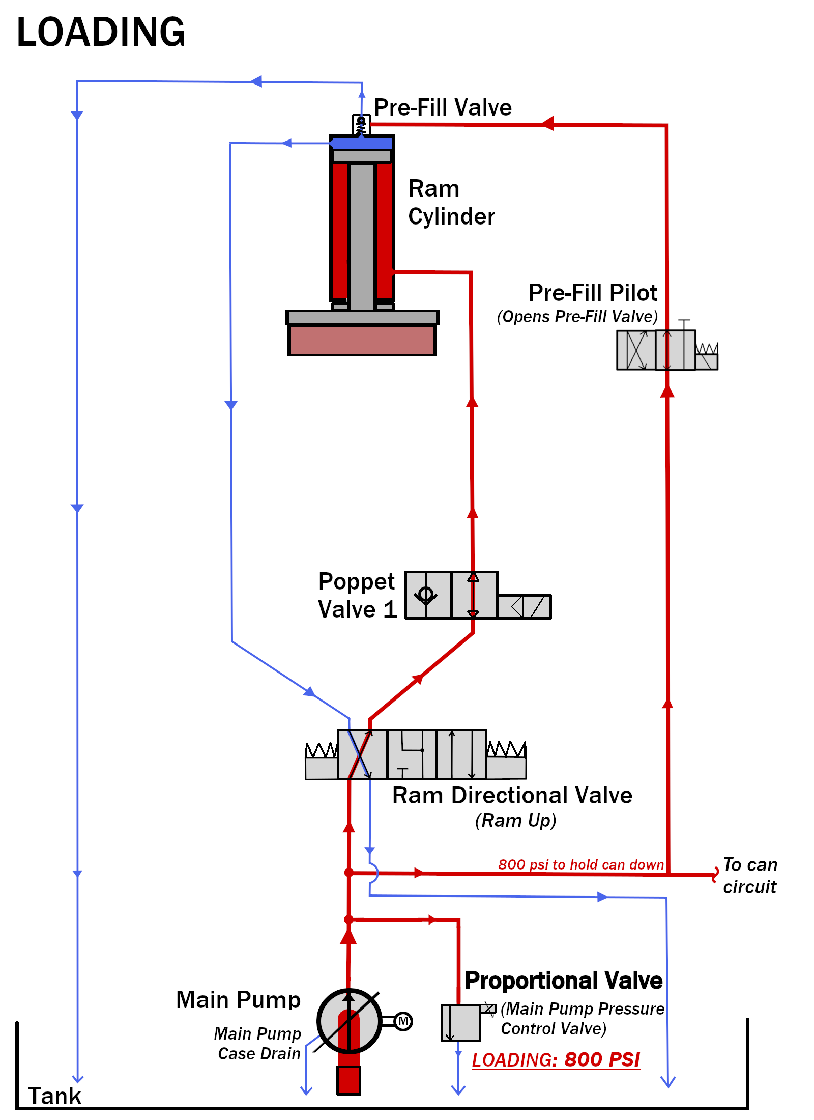
- Loading
- Ram Down (Free Fall)
- Pressurizing (Extraction)
- High Pressure (For Presses with Booster Pump)
- Ram Decompression (For Presses with Booster Pump)
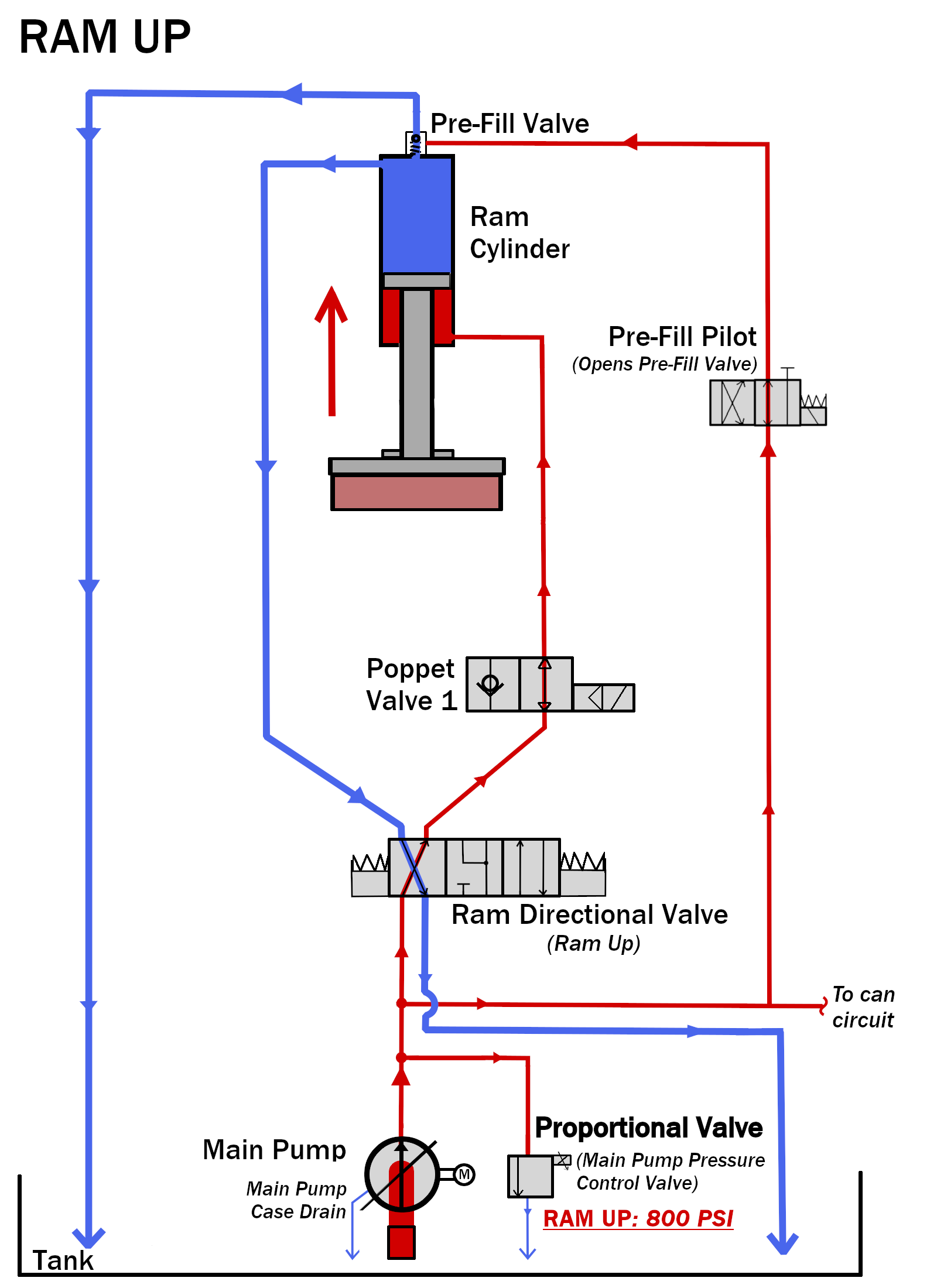
- Ram Up (Discharging Goods)
Note:The following illustrations are simplified representations of the hydraulic schematic. The hydraulic fluid flows through more components than are shown in the illustrations. Only the components that alter the flow are included.
1. Idling (Waiting to Load)Idle pressure is determined by the setting of the idle pressure setting on the main pump. The Idle pressure is typically set at 400 psi.
The ram can drift down slightly while in idle. The can is in the down position and has the 400 psi on the top of its pistons.
For more on the can circuit see the
SS Press Hydraulic Circuit - Can knowledge article.
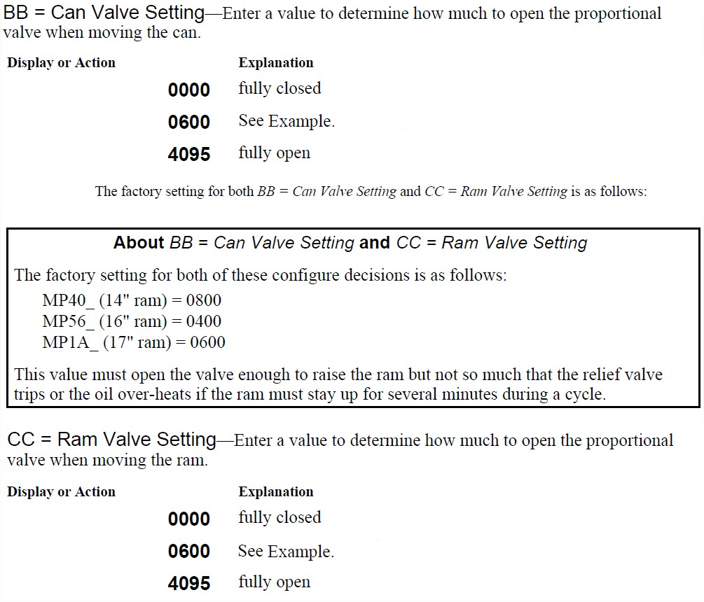
The press is ready to receive a load when the ram is full up and the can is fully down. The Ram Full Up and Can Full Down proximity switches must be made.The proportional valve is adjusted to allow for 800 psi determined by the Can Valve Setting configure decision. The pressure is used to hold the can in the down position (1/16" off of the bed) during the loading process. See
Supplement 1 below for more information on Can Valve Settings.
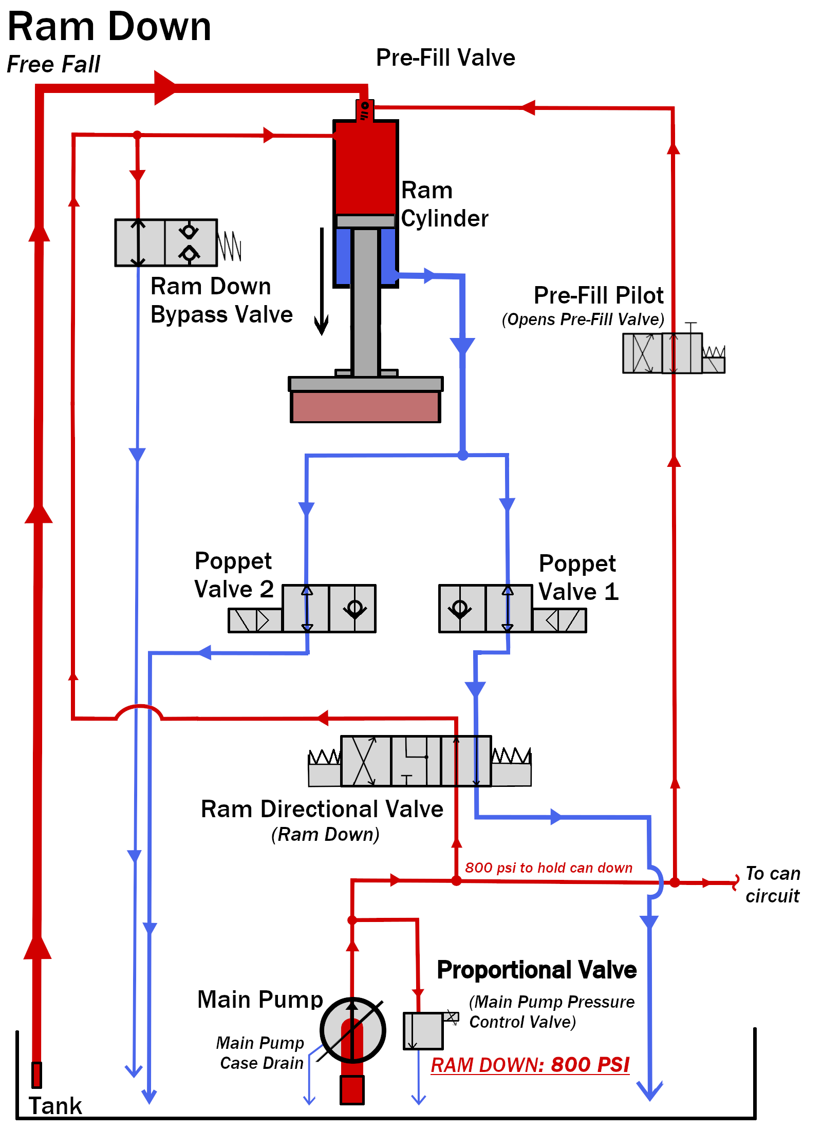
The Ram Directional Valve is shifted to the Ram Down position and the poppet valves solenoids are powered to allow fluid to flow from the bottom of the cylinder to the tank. The reason this stage is referred to as 'Free Fall' is because the weight of the ram is what lowers the ram down.
It is not pressurized down. The Pre-Fill Valve does pilot open in free fall. But, the ram will free fall even if the prefill valve is closed. The valve will open due to the weight of the ram. Most of the fluid that fills the vacancy in the top of the cylinder is suctioned from the tank through the Pre-Fill Valve and goose neck. The speed at which the ram moves down is limited by the flow rate of the poppet valves on the bottom of the cylinder.
So, to be clear...the ram will fall if you open a poppet valve. As soon as the fluid can come off the bottom of the piston through a poppet valve, the ram will fall.
The main pump is being regulated at 800 psi by the Proportional Valve to hold the can in the down position.
The normally open Ram Down Bypass Valve keeps the pump from generating significant pressure on the top of the ram while it is being lowered into pressing position. The Bypass is a normally open valve that drains to tank limiting the pressure on top of the ram to approximately 200 psi.
There is no setting for the Ram Down Bypass Valve. The flow through the size of the hole in the valve is what allow a max pressure of 200 psi.The Pre-Fill Valve is piloted closed when the Ram Inside Can proximity switch is made.
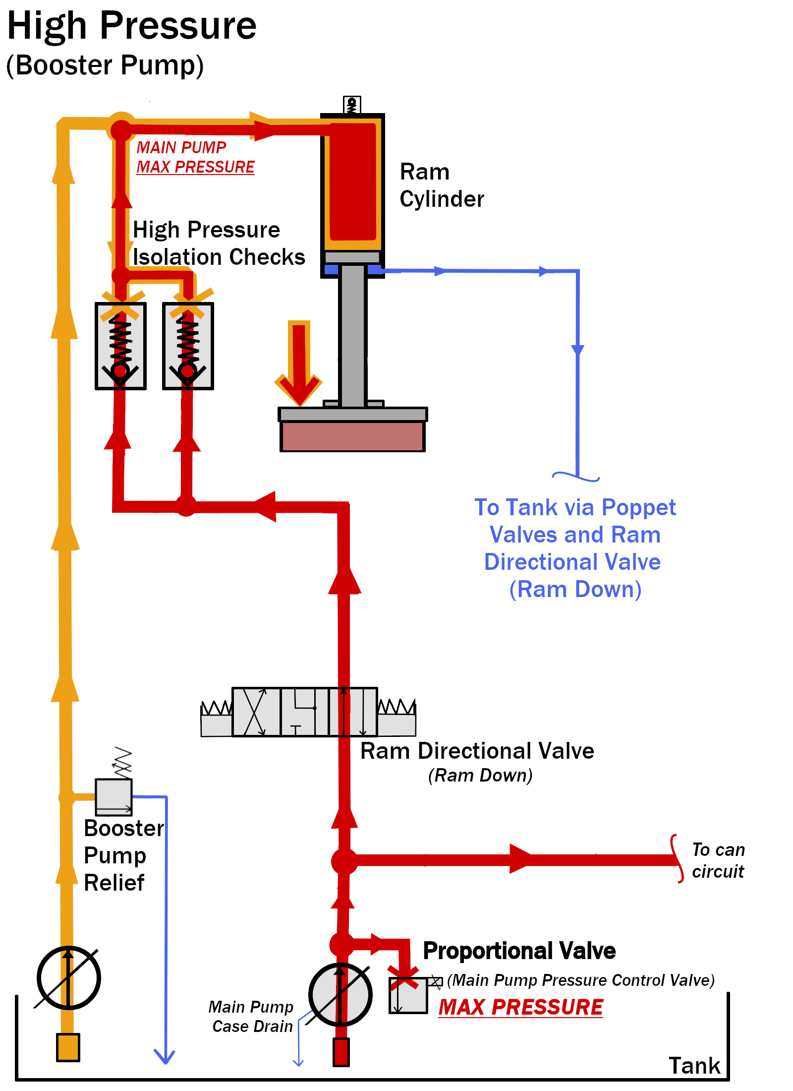
If you have a booster pump see the next step, 5 High Pressure. The Pre-Fill Valve is closed to allow pressure to develop on the top of the piston. The Proportional Valve closes and tells the Main Pump to ramp to maximum pressure.This pressure is set by the horse power compensator on the pump. The max pressure setting is dependent on the model of the press.
The Booster Pump is turned on at the same time that the Main Pump begins its ramp up to maximum pressure. This helps move more fluid to the top of the piston faster. The check valves are forced closed once the Booster Pump Pressure overcomes the Main Pump Pressure (when MP max pressure is reached). This allows the Booster Pump to achieve its max pressure with out back-feeding the Main Pump.
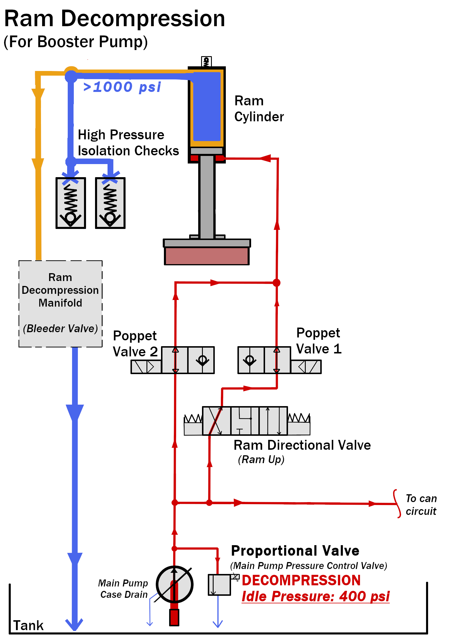
The Booster Pump is turned off and the high pressure is relieved through the Ram Decompression Manifold. The High Pressure Isolation Check Valves are closed to separate the high pressure built by the booster pump from the rest of the system. The Isolation Checks are piloted back open to allow flow once the pressure is below 1000 psi.
The Pre-Fill Valve is piloted open to increase flow to tank. The main pump lifts the ram with the Ram Valve Setting pressure that is configured on the press. See
Supplement 1 below for more information on Ram Valve Settings.