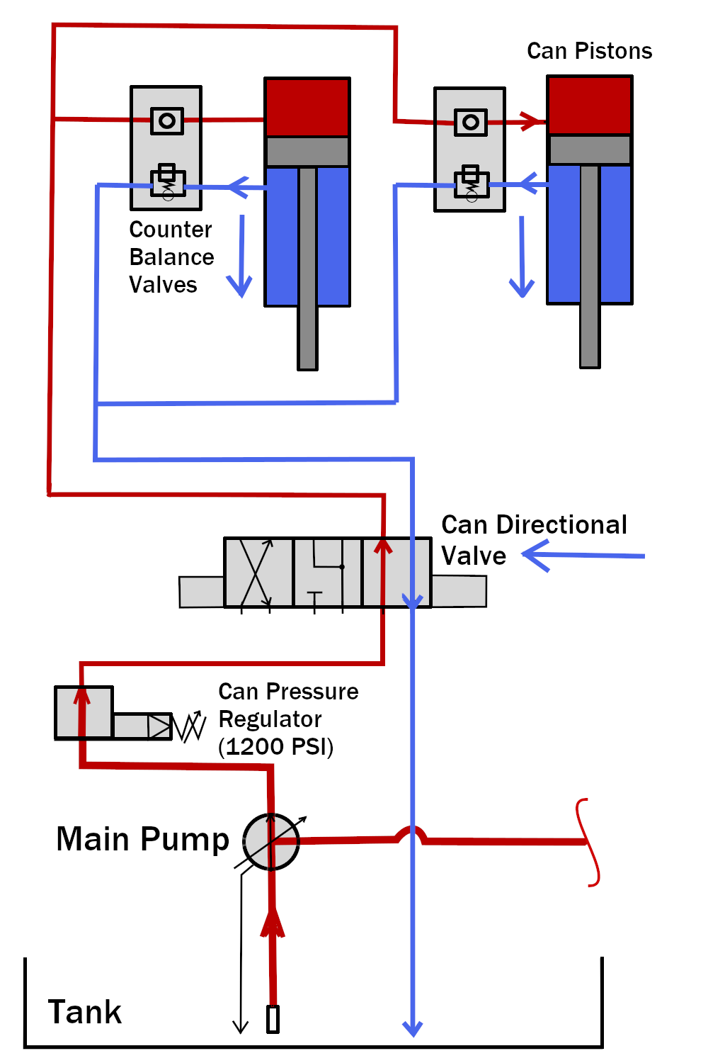
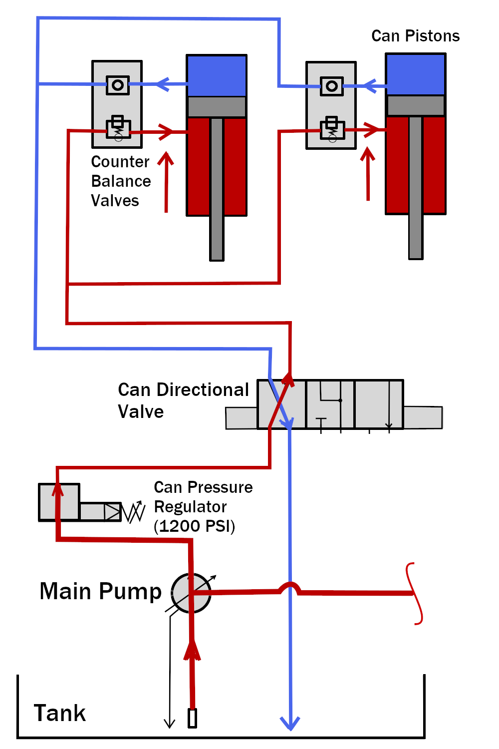
The hydraulic circuit for the can pistons is fairly simple when broken out of the larger circuit. The up and down modes are illustrated in the images below.
For information on the ram circuit, see Single Stage Press Hydraulic Circuit - Ram
During the ram down command, the can directional valve shifts to route the pressurized hydraulic fluid to the top of the can piston and the fluid from bottom to the tank. The Can Pressure Regulator is set to 1200 psi. The regulator is only active during the ram pressurization step to keep the high pressure fluid going to the top of the ram from damaging the can pistons. If only the can is moving then the control dictates a can pressure as set in configure as the "can valve setting". The counter balance valves ensure that both pistons move at the same time so that the can moves evenly on both sides. These counterbalance valves hold the load from falling at different rates due to gravity and differing friction loads in the 2 cylinders.
Can Up:
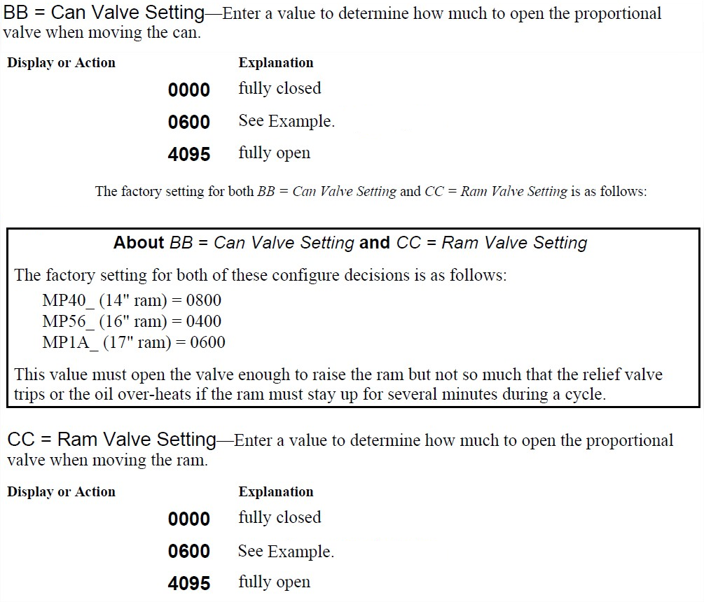
The can directional valve shifts to the can up position. Pressure during the Can Up step is determined by the Can Valve Setting configured. See supplement 1 below for more.
These settings are in machine configure and are accessed in CONFIGURE.