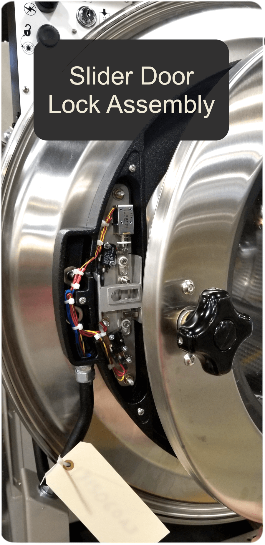
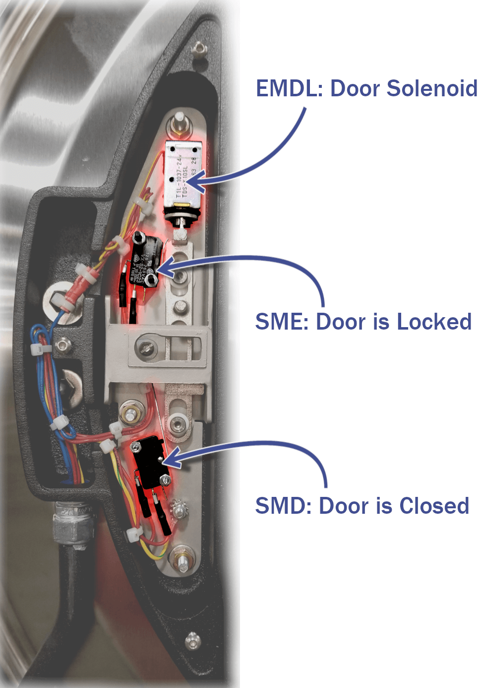
Door Lock Electrical Components:
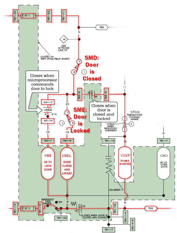
SMD: Door is Closed Switch
The SMD micro switch is made when the door is closed and the handle is turned clockwise.
EMDL: Door Solenoid
The door solenoid pulls the slider up (locked) or pushes it down (unlocked). The slider makes the SME switch indicating that the door is locked.
SME: Door is Locked Switch
SME (the door is locked switch) pulls in CRDL which enables the inverter contactor and the motor.
These components are called out in the start and door circuits below.
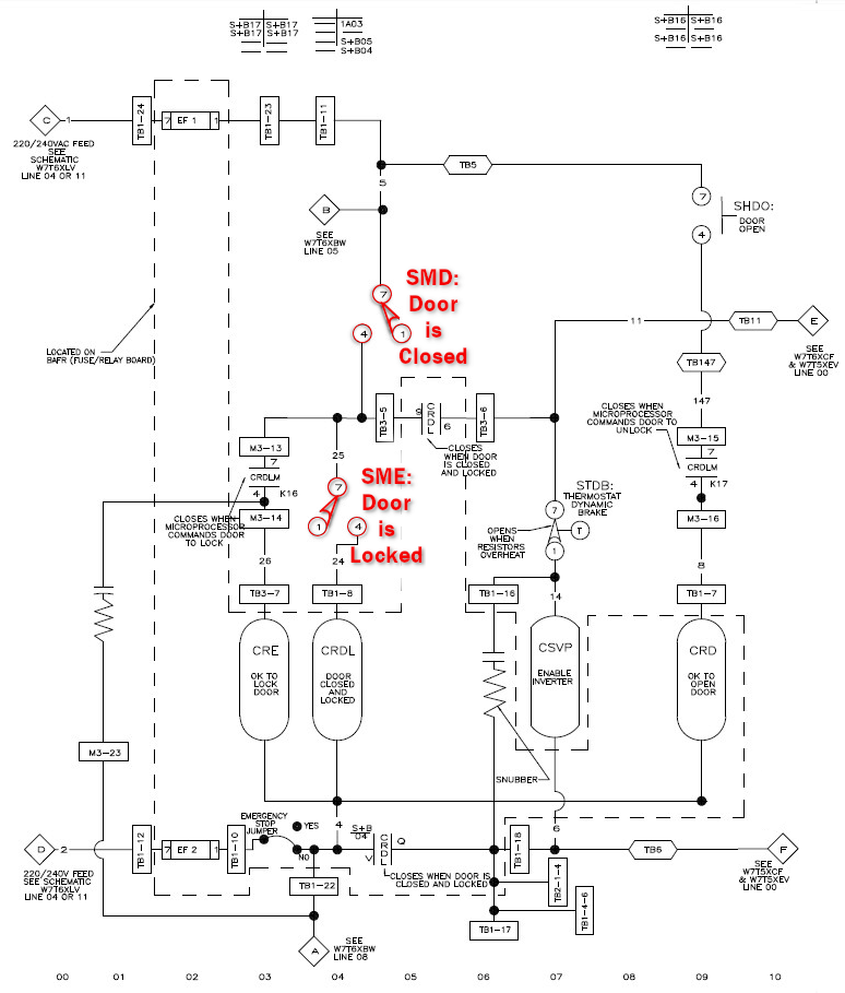
The Door Circuit (LOCKING DOOR)
To operate the machine we need to complete the 220/240v AC start circuit through the two micro-switches to pull in the CRE (OK TO LOCK DOOR) and CRDL (DOOR IS CLOSED & LOCKED) relays. CRE also needs the K16 relay located on the output board to close to complete the lock door circuit.
The contactor that sends drive power to the inverter pulls in through a normally open contact on the CRDL relay. (YOU CANNOT GET POWER TO THE CONTACTOR OR INVERTER IF THE CRDL RELAY IS NOT PULLING IN, CONFIRMING THAT THE DOOR IS CLOSED AND LOCKED).
Malfunction Symptoms:
If you are getting display power but you notice that the contactor is not pulled and the inverter is not powered then make sure the door is closed and locked. If it is then try swapping the CRDL relay with the CRD to quickly check if it is a bad relay. The start circuit is illustrated below. The components highlighted in green are located on the BAFR (Start, Fuse, Relay, BARF) Board.
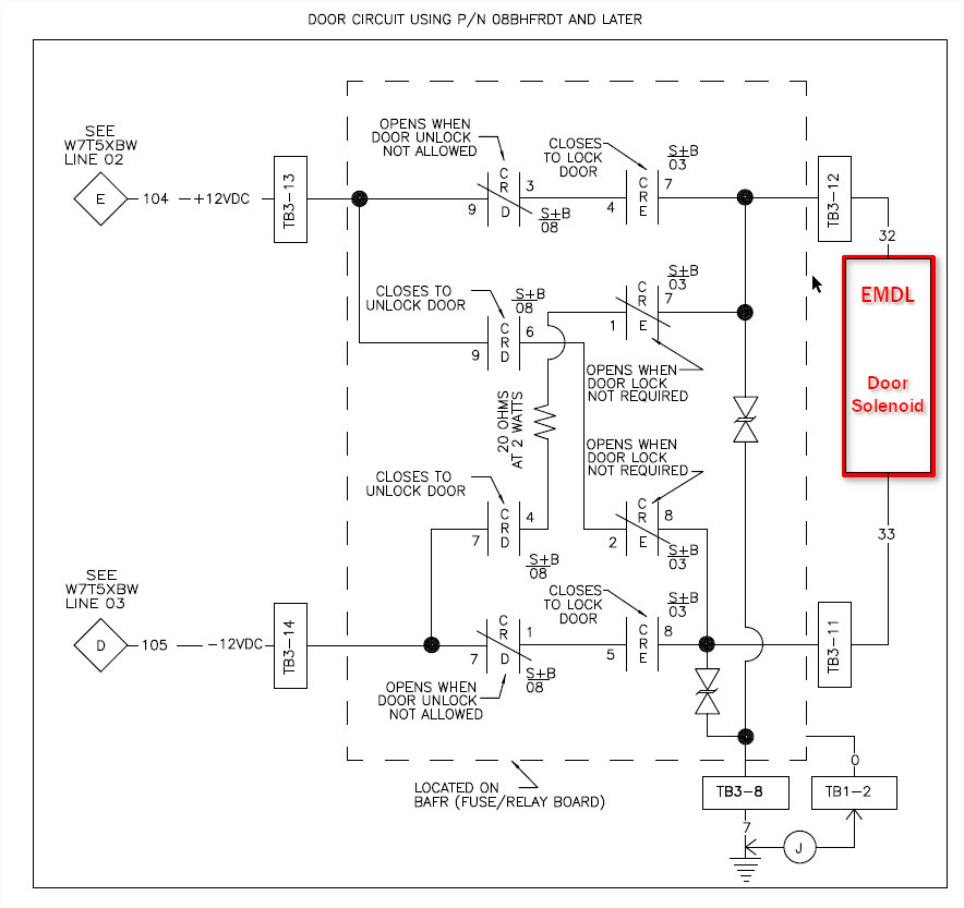
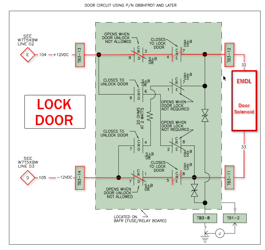
Normally open contacts on CRE close to energize EMDL. In the illustration below we can see (in red) the active circuit to lock the door. This pulls the slider up and locks the door, making SME, energizing CRDL (door is locked) and prevents the door handle from being turned.
The door actually stays locked (slider in up position) magnetically. So, even if power is lost to the machine the door stays locked.
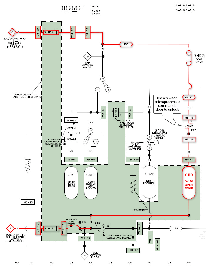
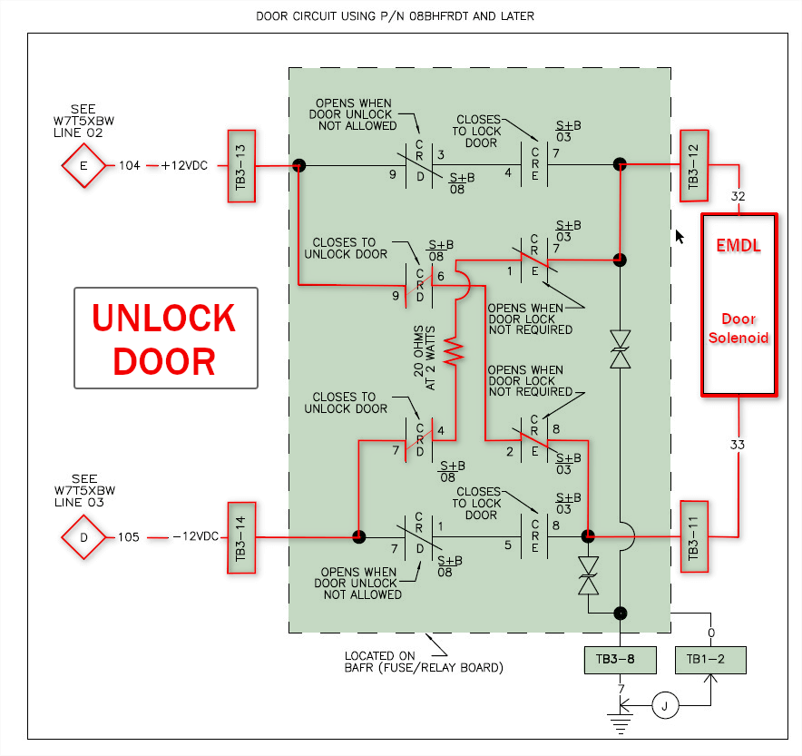
Door Circuit (UNLOCKING):
To allow the slider to fall, the lock solenoid has to overcome the magnet and push the slider downward. This is done by reversing the DC current on the EMDL solenoid. When CRE is off AND CRD pulls in, we feed power to unlock EMDL. SHDO (the Push to Unlock Button) feeds CRDLM (the microprocessor output) to enable the door to open.
Related Articles:
Video - Understanding the Doorknob Interlock Mechanism
http://milnortechnicalsupport.force.com/pkbmilnor/articles/Milnor_Article/Understanding-the-Doorknob-Interlock-Mechanism/?q=door+lock&l=en_US&fs=Search&pn=1BAFR - 08BHFRDT Retrofit Kit
http://milnortechnicalsupport.force.com/pkbmilnor/articles/FAQ/BAFR-08BHFRDT-Retrofit-Kit/?q=bafr+board&l=en_US&fs=Search&pn=1
Keyword Search: Slider lock, door lock, interlock, door knob, door lock assembly, BAFR board, start board, BARF board, CRDL, CRE, CRD, Door Circuit, Start Circuit, Slider Door Lock Assembly, door switch, door lock solenoid
