08BH188BT / 08BH188BXT processor board replacement notes
A newly designed processor board (08BH188AT and its future successors) is now available to replace the 08BHEPxx processor board. This board was used on EPXpress and EPPlus machines for a number of years.
NOTE: 08BH188AT has been discontinued. It has been replaced by 08BH188BT. If desired, 08BH188AZ (repaired 08BH188AT) is presently available. Email parts@milnor.com to confirm inventory levels
The new board is only compatible with display boards that use a RS485 serial data connection. Older displays that use TTL connections (3 wires on a small white plug) will not be compatible with the new processor. So, a new display will have to be retrofitted to machines with TTL only displays.
Some older displays have both TTL connections and RS485 connections. If the TTL connection was used on the older processor board it is possible to use the RS485 connection with the new board IF you make or buy a RS485 cable (pn 10M75V7JDS – 72” long).
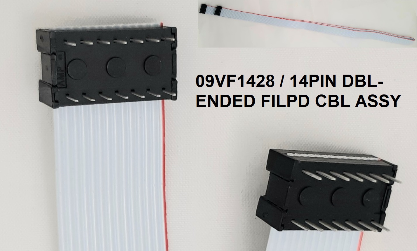
Some older switch panels will have the 14 conductor Ribbon cable soldered to the board. This may require a new 14-pin cable. We have two cables depending on what you need.
09VF1428 is a 36" cable with DIP connectors attached to both ends.
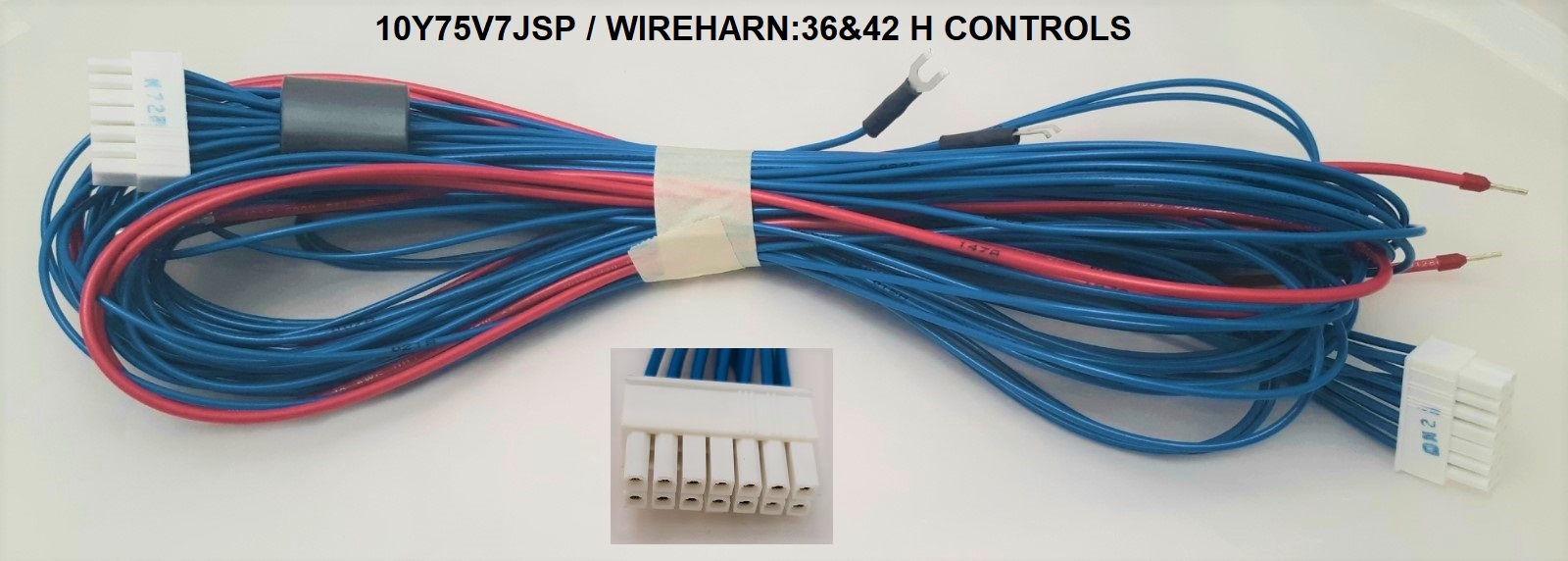
10Y75V7JSP is a 60" cable with Molex Mini-Fit plug.
The new processor board has screw terminals to replace some of the connectors and pins used before. This requires the installer to cut the ends of the wire from the connector and attach the wire directly to the board screw terminal.
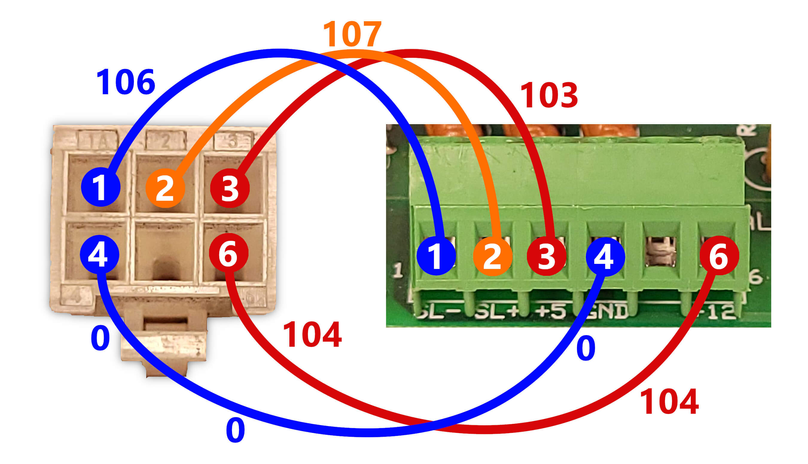
A schematic for the machine would be useful when replacing the old board, but it should be this simple. Also, The wiring changes are illustrated below.
- The 5VDC (103), GND (0), 12VDC (104), SER- (106) and SER+(107) wires are cut from the connector M1, stripped and placed on the new board screw terminals. Cut and strip the wires one at a time and connect to the new processor board.
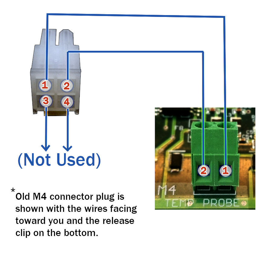
- The temp probe wires on M4 are cut at the connector and tied to the screw terminals at the new M4 header.
- The 5VDC and ground wires are not used on M4 and can be cut and capped.
The EXT-SIGNAL connector is not used.
Setting Voltage:
Set the 12VDC power to 12.80 volts. The new board has onboard 5VDC regulation so there is no need to adjust the 5 volt supply.
HARDWARE for mounting the new board:
The new board is thicker than the old. The standoffs for the old board will not lock to the new board, so, screws and nuts are provided for the attachment. If you use metal screws, only use them on the edge of the new board, not in the middle.
The old M1 and M4 plug connectors are shown with the wires facing away from you and the release clip on the bottom. These connectors have ridges on the side opposite to the clip that indicate the
pin numbers. On the wire entry end of the plugs there are numbers embossed in the connector.
M1 Plug to Screw Terminals Change Out:
 Changing Out Temperature Probe:
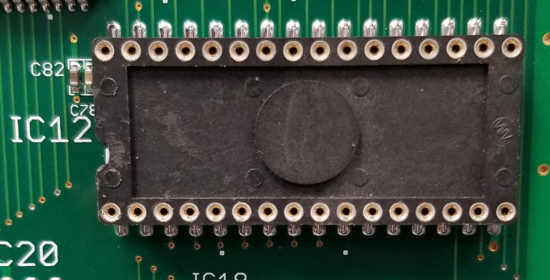
CAUTION: before applying power to the new processor board, install the EPROM (IC12) aligning the notch in the end of the chip with that of the socket and connect ONLY the power (M1), Temp Probe (M4) and the display (M22). With these connections made apply power and check the display. If the board is correctly connected and the EPROM installed correctly, the display should show normal text. This proves that all the wiring is correct. Remove the power to the machine and complete the wiring of the processor board.
The socket for the machine software is shown below. Be careful not to bend pins when inserting the software in this socket! Check your work!
Is My Display Compatible?
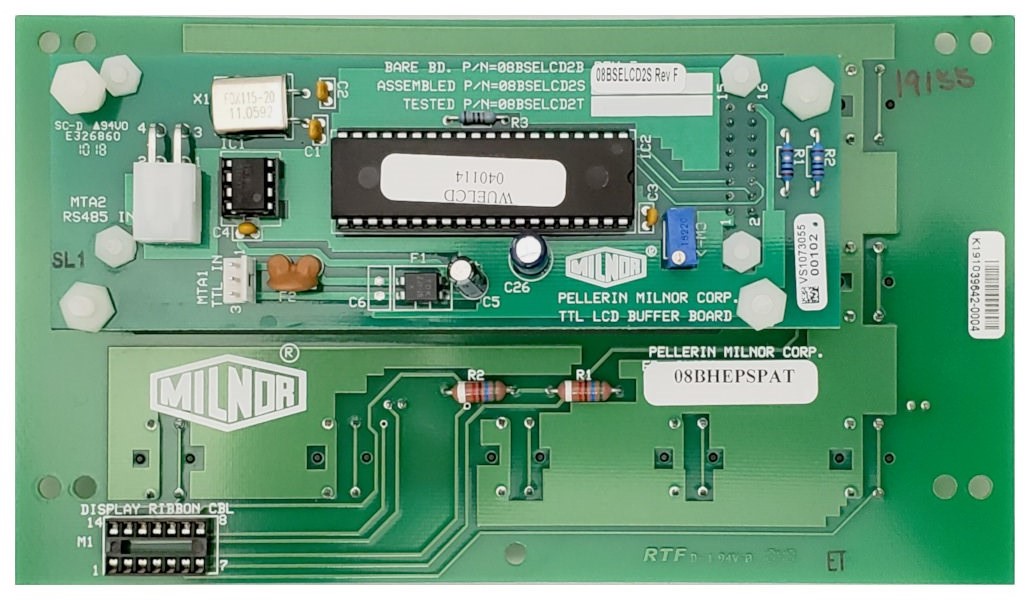
As mentioned above, the display requires a RS485 connector. See the display boards and notes below to determine if you can use your existing display. If you cannot use your existing display, use display part number 08BHEPSPCT (or replacement). One way to know if the display uses the TTL connector is to look at the processor card for M21. If there is a wire on this connector then the machine is equipped with a TTL compatible display and you will have to determine which one below to know if the display is to be replaced for compatibility with the new processor.
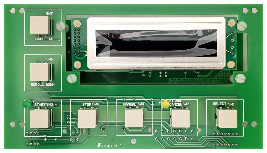
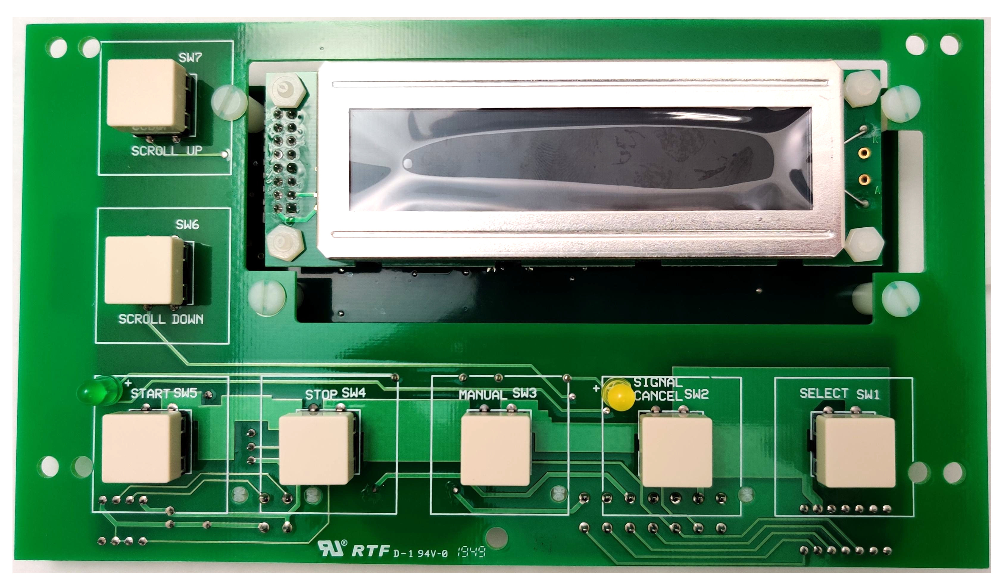
- Displays with small black buttons may need different part number kits to replace the display. For info on displays with small black buttons, click HERE
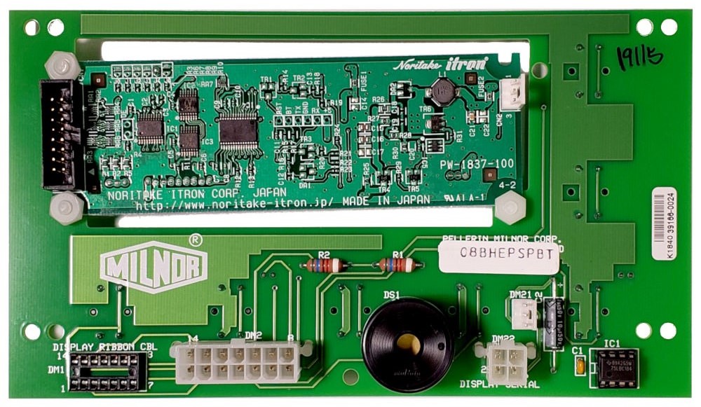
If your current display is the 08BHEPSPT, you would replace it with the 08BHEPSPBT and use the RS485 connector for serial connection (when reusing the same processor board).
If your current display is either the 08BHEPSPAT or 08BHEPSPCT, you would replace it with either the 08BHEPSPCT or 08BHEPSPDT and use the RS485 connector for serial connection.
In the worst case scenario, you will need a new display and switch panel (08BHEPSPCT and RS485 harness 10Y75V7JDS). It is possible to use a new display on an old switch panel. For example, you could install a 08BSELCD2T on an older switch panel board. Use a step bit to drill out the holes for the larger switches. This may help avoid changing the switch enclosure and overlay.
08BHEPSPT FRONT SIDE (Noritake) |
08BHEPSPT BACK SIDE (TTL only) |
This
08BHEPSPT board will not be compatible with a new style processor since it has no RS485 connector. It must be replaced with a 08BHEPSPCT or later board.
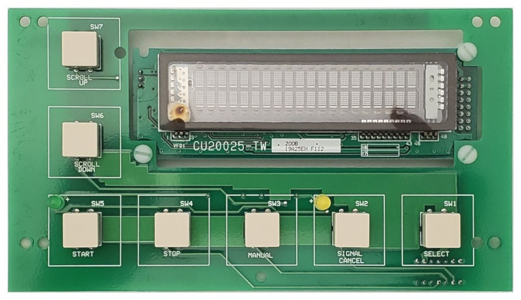
08BHEPSPBT FRONT SIDE (Noritake) |
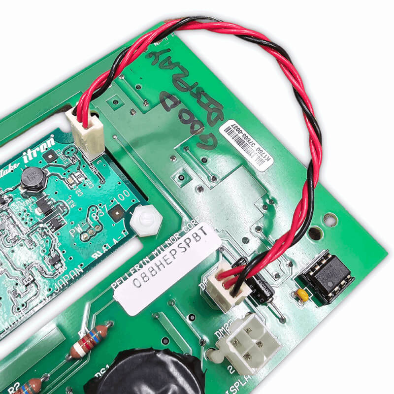
08BHEPSPBT BACK SIDE (Serial and TTL Jumper) |
This board has both a RS 485 connector and a TTL connector. If the previous processor was wired with a TTL cable, you will need a RS485 cable and also to jump the TTL wiring from the switch panel connector DM21 to the similar connector on the back of the display.
CAUTION: the TTL cable must be pinned in reverse order… pin 1 to pin 3 and pin 3 to pin 1. Otherwise the RS485 transceiver in IC1 will be destroyed.
If needed, add RS485 Transceiver
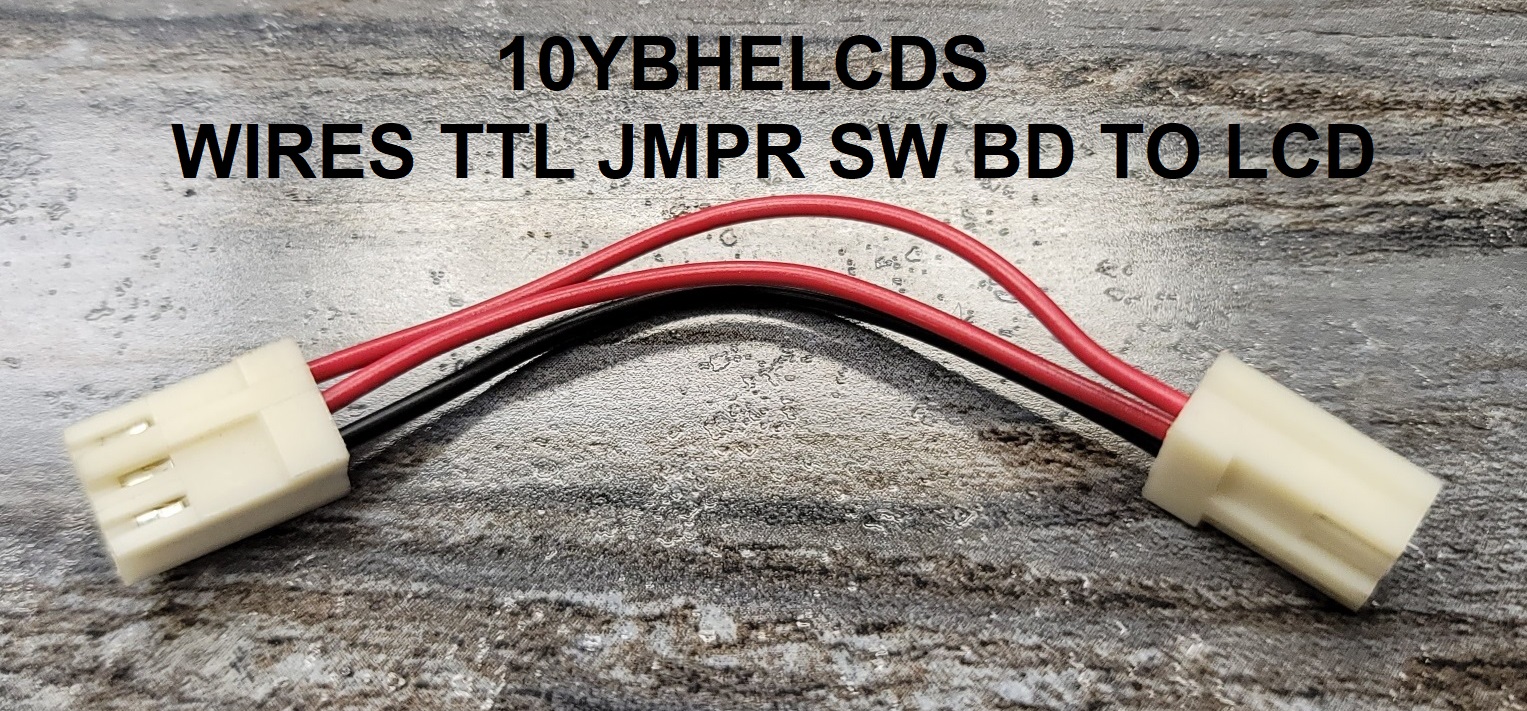
08CIF3696T into the IC1 socket. The TTL jumper from the switch panel to the LCD display is part number
10YBHELCDS.
  |
08BHEPSPAT FRONT SIDE |
08BHEPSPAT BACK SIDE |
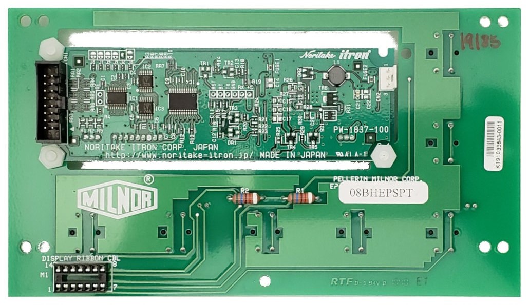
08BHEPSPCT FRONT SIDE |
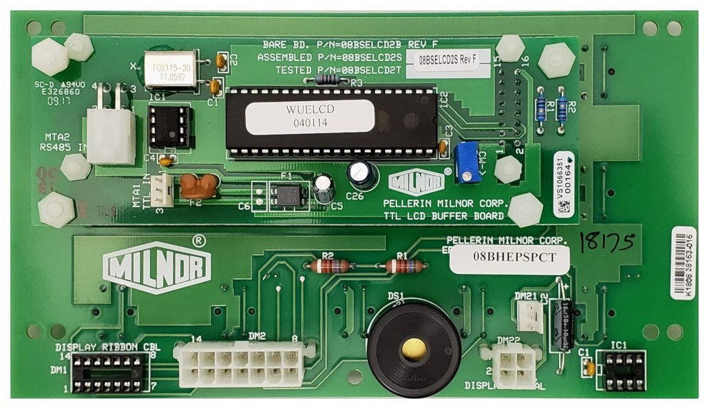
08BHEPSPCT BACK SIDE |
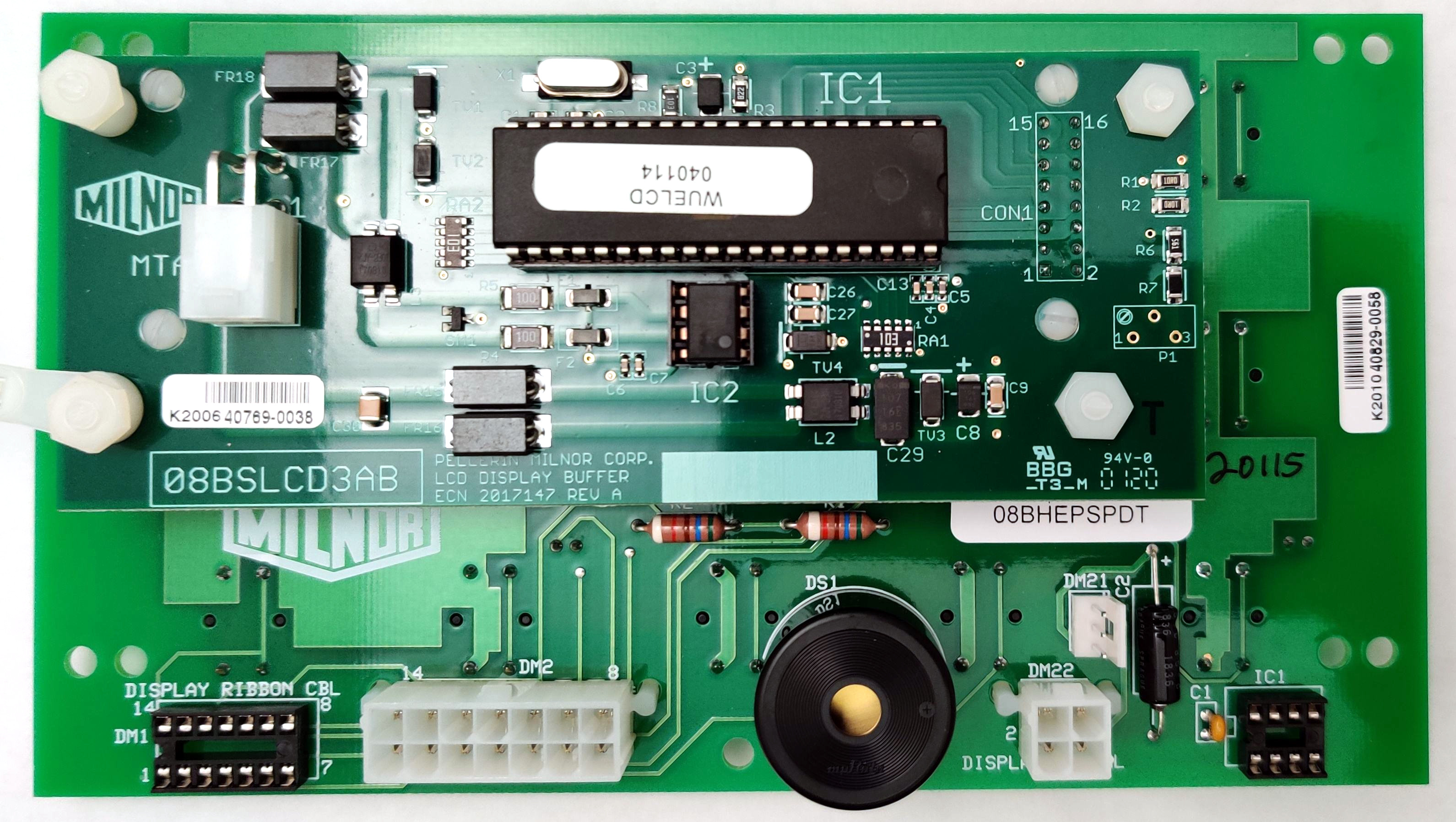
This 08BHEPSPCT display is compatible with all processor boards. It has both TTL and RS485 connectors. Using the 08BH188AT processor or later, the RS485 cable should be plugged directly onto the back of the display (MTA2) rather than onto the switch panel board. You must also remove the TTL jumper wire between the display and switch panel board. Also make sure that the transceiver is installed on the display board IC1. If it's not, add RS485 Transceiver 08CIF3696T into the IC1 socket.
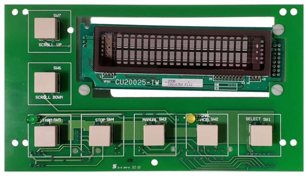
08BHEPSPDT FRONT SIDE |
08BHEPSPDT BACK SIDE |
The 08BHEPSPDT is the newest display, which takes the place of the 08BHEPSPCT. Using the 08BH188AT processor or later, the RS485 cable should be plugged directly onto the back of the display (MTA2) rather than onto the switch panel board. Also make sure that the transceiver is installed on the display board IC1. If it's not, add RS485 Transceiver 08CIF3696T into the IC1 socket.
For reference: Display types and usage.
VFD
| 08BHEPSPT | EP+ SWITCH PANEL BD>TEST | 30" machines |
|---|
| 08BHEPSPBT | BD:EP+ SW PANEL VER2->TEST | 36" machines and up |
|---|
LCD w/backlight
| 08BHEPSPAT | EP+ SWPNL BD W/LCD>TEST | 30" machines | 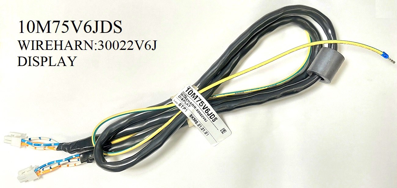 |
|---|
| 08BHEPSPCT | EP+ SWPNL VER2 W/LCD>TEST | 36" machines and up | 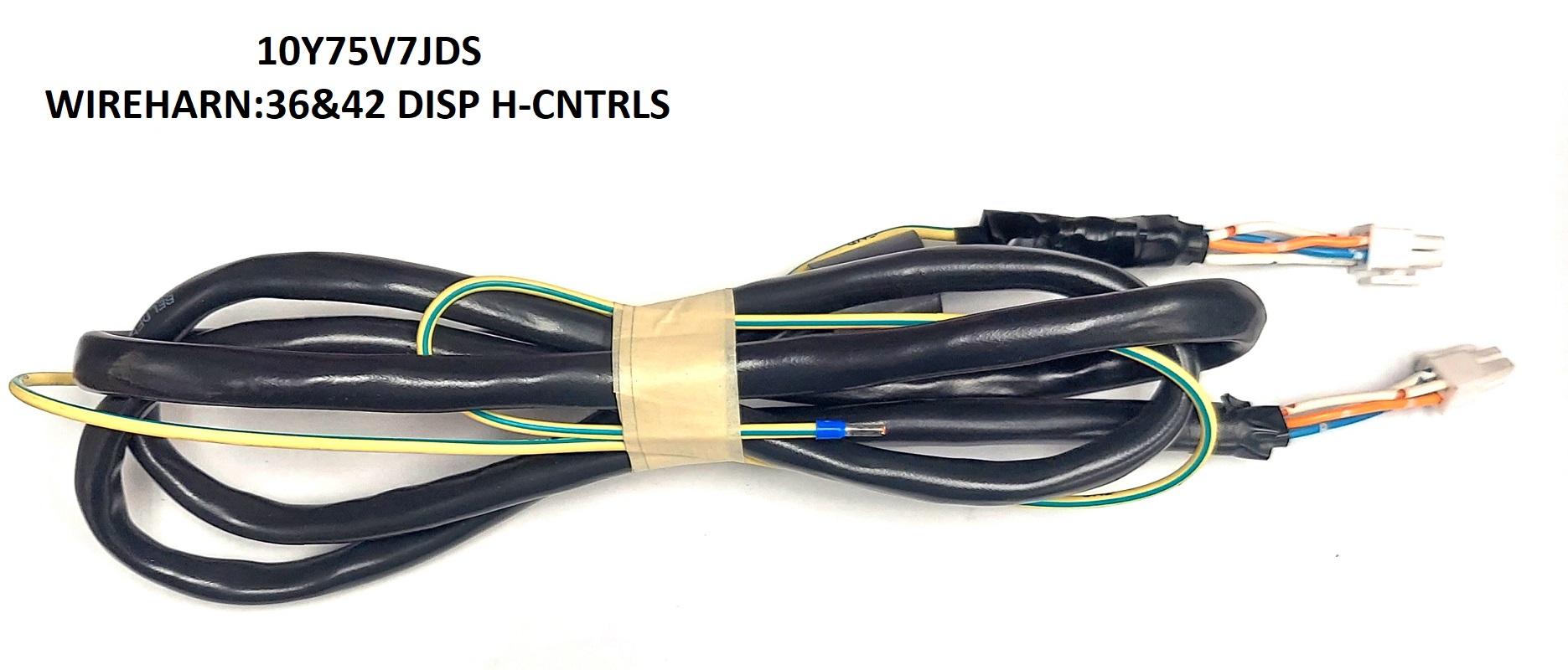 |
|---|
Display: 08BHEPSPBT
Processor Kit plus hardware and harness: KXMIC00188
14-pin Ribbon Cable 36": 09VF1428
14-pin Molex Mini-Fit Cable 60": 09BC14NFBP
Display Harness: 10M75H7JDS (4 pin conductor shielded)
Graphic Overlay: 01 10657X
Retro Fit Harness (red connector): 10YAMTA24CP
Any time a 08BH188AT or 08BH188BXT board is being ordered/replaced/installed there are a few questions you should ask the customer.1. What is the current software and version on the processor? (The current software may not be compatible with the new processor, display, or model of machine.)2. What plug connector is being used for the display? (The M21 uses an 3 wire TTL connector and M22 uses an 4 wire connector RS485. If machine is using the M21 3 wire TTL connector, then it has to be replaced with the M22 RS485 4 wire connector because the new processor does not support the TTL port.)3. Is the ribbon cable on the display plugged in or solder to the board? (If it is soldered, the display/keypad needs to be replaced along with a new overlay.)4. Are the buttons on the key pad round or squares? (If buttons are round the display/keypad needs to be replaced along with a new overlay*.)5. What color are the plug connectors on M3 & M5? ( If plugs are white it is ok and move on the next question. If they are red/orange, it will be replaced by kit KXMIC00188. Which comes with the wire harness to replace M3 & M5, processor 08BH188AT and wiring instructions.)6. When was the power supply last changed? (If it is unknown or voltage output is not able to be regulated replace the power supply.)*NOTE: If the display/keypad board needs to be replaced some modifications to the button holes on the housing have to be made. This can be done by using a unibit to open the hole to 3/4", which is the size needed for the new square button to fit. If the customer does not want to make the modifications for some machines it is possible to order a new complete housing with boards and cables included with the exception on the RS485 cable.)If the machine is a HxJ style machine additional questions need to be asked. 7. Does the machine have a door unlock button? (The answer to this question is going to determine what software and overlay that needs to be ordered.)(If equipped with door open button WUH7JA 2200ZD, Overlay EP-Plus HxJ with door open button 01-10657Y)(If not equipped with door open button WUH7JA 9700CX, Overlay EP-Plus HxJ with no door open button 01-10657X) Parts Processor boards08BH188AT for EP-Plus controller.08BH188BXT for EP-Express controller.KXMIC00188 for EP-Plus controllers that have red/orange M3 & M5 plug connectors. KXMIC188AT is the hardware kit and needs to be sold with the above 3 numbers. Display/keypad boards08BHEPSPAT for 30015/22 T, V, & H machines 08BHEPSPCT for 36, 42, 48 & 30022X8J machines Complete Display/keypad housing kits (does not come with RS485 cable)KKTEPXDC01 for EP-Express controlsKKTEPPDC01 for EP-Plus controls 30022Vxx